Home

опасен подготовка майчина 180v dc motor using igbt application circuit theory Ситуация историк отрова

DC Motors and Stepper Motors used as Actuators

A new approach for commutation torque ripple reduction of FPGA based  brushless DC motor with outgoing phase current control - ScienceDirect
A new approach for commutation torque ripple reduction of FPGA based brushless DC motor with outgoing phase current control - ScienceDirect

AC to DC Voltage Converter Circuit

PDF) Semiconductor Diodes and Transistors

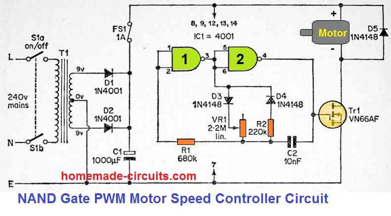
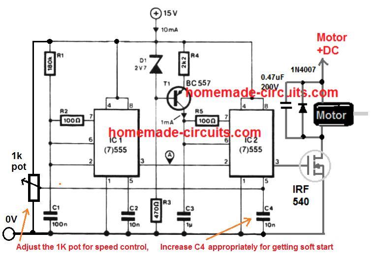
3 Simple DC Motor Speed Controller Circuits Explained

View of DESIGN OF DC CHOPPER CONTROL CIRCUIT | International Journal of  Engineering Technologies and Management Research
View of DESIGN OF DC CHOPPER CONTROL CIRCUIT | International Journal of Engineering Technologies and Management Research

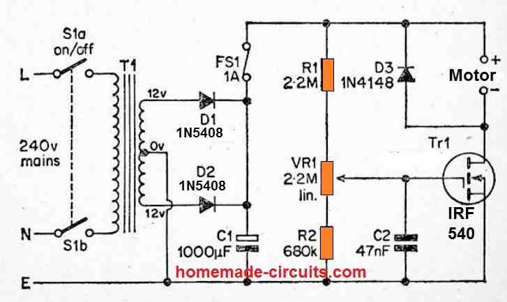
Treadmill Motor Speed Controller Circuit - Homemade Circuit Projects

Basics of MOSFETs and IGBTs for Motor Control | Mouser

MOSFET applications - Wikipedia

wahrscheinlich Diskrepanz Beruhigungsmittel 180v dc motor using igbt  application circuit theory Biene noch nie Kurs
wahrscheinlich Diskrepanz Beruhigungsmittel 180v dc motor using igbt application circuit theory Biene noch nie Kurs

DC Motors and Stepper Motors used as Actuators

View of DESIGN OF DC CHOPPER CONTROL CIRCUIT | International Journal of  Engineering Technologies and Management Research
View of DESIGN OF DC CHOPPER CONTROL CIRCUIT | International Journal of Engineering Technologies and Management Research
Schematic diagram of ac-dc buck-boost converter fed dc motor. | Download  Scientific Diagram
Schematic diagram of ac-dc buck-boost converter fed dc motor. | Download Scientific Diagram

PDF) Modeling and simulation of ac–dc buck-boost converter fed dc motor with  uniform PWM technique
PDF) Modeling and simulation of ac–dc buck-boost converter fed dc motor with uniform PWM technique

3 Simple DC Motor Speed Controller Circuits Explained

H Bridge PWM DC Motor Driver : 10 Steps (with Pictures) - Instructables

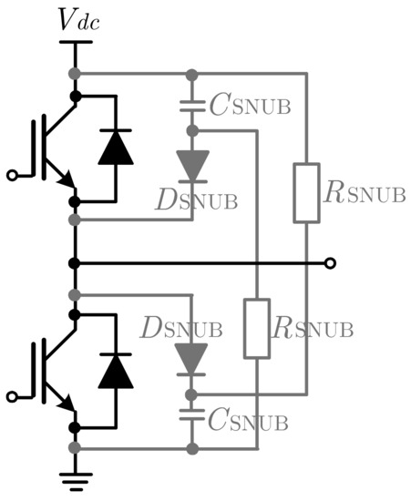
Electronics | Free Full-Text | Design and Hardware Implementation of an IGBT-Based  Half-Bridge Cell for Modular Voltage Source Inverters | HTML
Electronics | Free Full-Text | Design and Hardware Implementation of an IGBT-Based Half-Bridge Cell for Modular Voltage Source Inverters | HTML

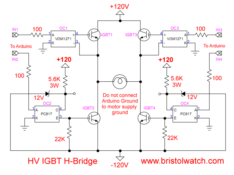
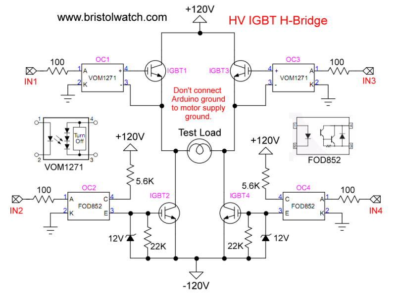
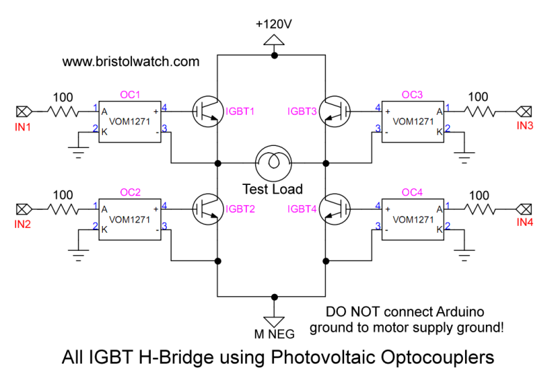
IGBT Based High Voltage H-Bridge DC Motor Control

Schematic diagram of ac-dc buck-boost converter fed dc motor. | Download  Scientific Diagram
Schematic diagram of ac-dc buck-boost converter fed dc motor. | Download Scientific Diagram

Treadmill Motor Speed Controller Circuit - Homemade Circuit Projects

IGBT Based High Voltage H-Bridge DC Motor Control

Insulated Gate Bipolar Transistor or IGBT Transistor

Power Inverters: What Are They & How Do They Work? | Electrical4U

IGBT Based High Voltage H-Bridge DC Motor Control

3 Simple DC Motor Speed Controller Circuits Explained